Dear all,
This is my first project in codesys and I am experiencing a problem with reading data via Modbus TCP in a setup where one controller (PLC in the form of an HMI panel running CoDeSys) is connected to two WAGO couplers:
Coupler 1 (Modbus_TCP_Slave_Pump_starter)
- 750-1405 – Digital Input, 16 channels (offset: 16#0000, using Read Discrete Inputs) –
 works
works - 750-430 – Digital Input, 8 channels (offset: 16#0002, using Read Discrete Inputs) –
 does not work
 - 750-530 – Digital Output, 8 channels (offset: 16#0000, using Write Multiple Coils) – works
- 750-474 – Analog Input, 2 channels (offset: 16#0000, using Read Holding Registers) – works
- 750-515-1 – Digital Output, 4 channels (offset: 16#0001, using Write Multiple Coils) – does not work
- 750-515-2 – Digital Output, 4 channels (offset: 16#0002, using Write Multiple Coils) – does not work
- 750-515-3 – Digital Output, 4 channels (offset: 16#0003, using Write Multiple Coils) – does not work
Coupler 2 (Modbus_TCP_Server_Mcc)
- 750-508 – Digital Output, 2 channels (offset: 16#0000, using Write Multiple Coils) – works
- 750-508 – Digital Input, 2 channels (offset: 16#0000, using Read Discrete Inputs) – works
- 750-1405 – Digital Input, 16 channels (offset: 16#0001, using Read Discrete Inputs) – does not work
- 750-430 – Digital Input, 8 channels (offset: 16#0003, using Read Discrete Inputs) – does not work
- 750-1504 – Digital Output, 16 channels (offset: 16#0001, using Write Multiple Coils) – does not work
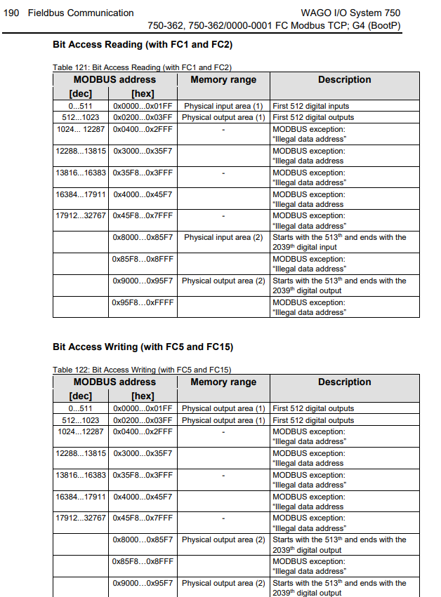
The issue is that only the modules configured with offset 16#0000 are working correctly. Any module configured with offsets greater than 16#0000 (e.g. 16#0001, 16#0002, etc.) does not reflect any state changes in the PLC program – even though the physical input signal is received (as confirmed by the input module LED turning on).
There are no Modbus TCP communication errors, and the connection is active. All address assignments and lengths have been configured according to WAGO documentation. I suspect this may be related to address range limitations, but I have not found any setting in CoDeSys or the WAGO documentation that would explain or resolve this behavior.
Are there any additional configuration steps required to allow Modbus TCP to correctly access input/output modules at offsets beyond 16#0000?
I have attached screenshots showing the full configuration of the Modbus server and variable mappings.
Thank you in advance for your help.