I have error when I try to connect with function block

Using the function blocks from the WagoAppPlcModbus library is different from using Codesys Modbus devices in the device tree.
You need only the master function block FbMbMasterSerial. The SimpleServer function block is when you want the controller acting as server.
Oh okay I understand but it still doesn’t work ![]() maybe my settings are wrong ?
maybe my settings are wrong ?
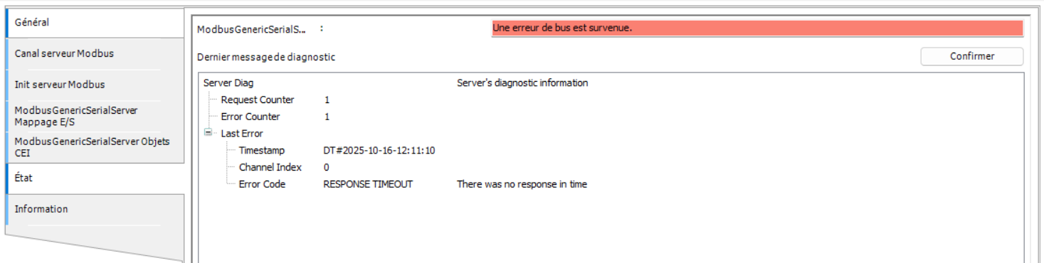
What errorcode do you get?

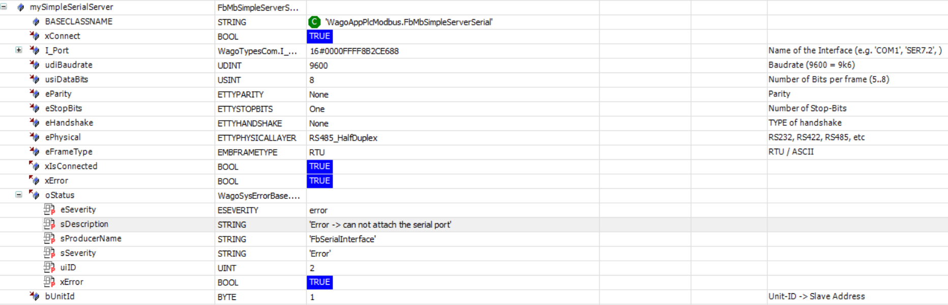
The xError attribute changes from true to false in loop
The errorcode is ‘Error time out’, that means there is no response from the device.
Either the address setting of the device is not correct, or the connection is not correct.
With address I mean the device address, not the register address. So check the address in the programm and also in the device.
The connection is more difficult, as there are several possible issues. Mostly, the wires are swapped, as the labeling of the connections are generally inconsisted, sometimes it is A & B, then D & /D and sometimes they are swapped. So easiest is to swap the two wires first, to see if it works then.
Then you should check if both sides are terminated with resistors, either hardware or in settings of both devices. Then if you have enabled the BIAS network or not. It should be activated only on one device, not both.
Okay thanks a lot I will check these paths


Your image makes it look like you are trying to use the 750-652 module for RS485 rather than the DB9 connector on the left side of the PFC300. Is this true? If so, you will need to use the WagoAppPlcModbus library instead of the CODESYS Configurator that you have shown in all your other screenshots. The Configurator does not have the ability to directly manipulate the 652 module.
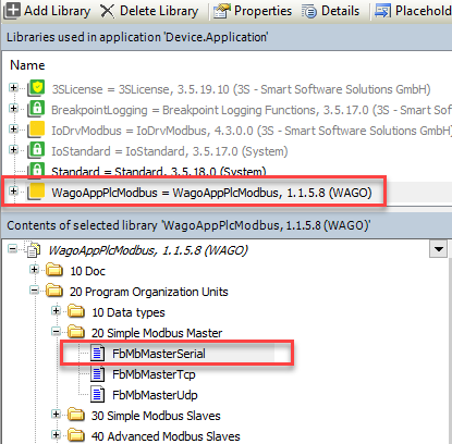
The Modbus_COM_Port can and should be completely removed from your project (since it isn’t doing anything with the 750-652 module) and just go with the FbMbMasterSerial function block in your program code.
Make sure the I_Port interface gets assigned the list “name” of your 652 module. As shown in your screenshots, it appears to be “_750_652_24”. The I_Port input to the function block should recognize this as a valid variable (i.e. no red error line).
Oh yes you’re right ! It’s true, I wasn’t using the module 750-652
Is like this okay ? :

For the uiReadAddress what address should I put ? Can I put “50512” (0xC550)? I found this value in the table modbus of the device I’m using : MODBUS tables of Countis_E43
At quick glance, yes that looks right. And I agree, 50512 would be your uiReadAddress value. Although since the device table shows 50512 as “reserved” with no data type, it might be true that you should start with 50514 instead.
In codesys, I have error timeout with code error 153
Is there a basic resistance on the modbus board _750_652_24 ? Because I think the problem comes from the connections to the modbus. We added 120 ohms on the wires but if there is already a basic resistance, it means that there would be an excess, could this perhaps explain the issue?
And also the cables are not armored, can it come from there?
Hi, can you post an excerpt of the wiring diagram? In your picture above it looks like there are two cables connected.
The wiring should be like this:

The 652 has no internal resistor, see manual. You can measure the resistance between A and B line. When both resistors are connected the resistance should be near 60 Ohm.
No shield/screen may be an issue if there is heavy EMC noise. How long is the cable to the energy sensor?
Hi Thruser, thanks for your reply
Here is the schema
schema_modbus.pdf (297.0 KB)
When we will measure the resistance & measure the cable I will give a feedback
NB: in the schema CPT is the energy sensor


Hello,
So on the left side the red cable and the black one are shorted together ?
Same on the right side ?
Yes, in the picture are are two wires at 1 and 5. But where are they connected to? Are they still connected as this picture is, according to the timestamp, already thre weeks old., e.g. there is also no 120 ohnm resistor visible?