Hi Folks,
I am having trouble with a CANbus 750-658 card. I can’t seem to read any canbus on it. I’ve tried many different configurations and the Can Status LED either stays red, or it will change to orange when in Auto Baud Rate mode. The CAN Rx LED also stays red. The card is configured with mailbox diagnostics on and mailbox size to 5 and the images size to 24 bytes. The device I have speaks at 1Mbps. I’ve tried both that setting and the Auto setting (and all other bauds). I have all filters turned off. I’ve tried both 2.0A and 2.0B Data formats. I’ve even switched modes, but I feel Sniffer would be the best bet to see data flow.
I do get error codes for the Mailbox Diagnsotics:
Error - Channel 0 - Mode SingleShot - Error Code 03E9 (100)
Warning - Channel 0 - Mode EventAppears - Error Code 03F1 (1009)
Error - Channel 0 - Mode EventAppears - Error Code 03F0 (1008)
Any help would be greatly appreciated,
With some further testing, If I remove the CAN-H and CAN-L wires from the unit the CAN Status LED goes green.
I had the same problem on a site and the problem was related to the termination resistor not being there.
Are you sure there is 120Ohm resistor between CAN-H and CAN-L at both end of the network ?
Thanks WagoIcard,
There is no 120ohm resistor… I wondered if this was an issue. The cable length is only maybe 2 meters. I’ll add and see. Thanks!
So the 120 Ohm resistor was added. I’m not sure this was the major issue but it should be done.
I ended up ordering a USB to CANbus converter and running a CAN software (cangaroo) on my PC. I could see TX sent from the WAGO 750-658 CAN card on the PC at different baud rates but nothing was being received on the Wago card. I then tried fiddling many parameters until I tried turning ON filters. these filters are turned ON by default for good reason - typically filters remove things you don’t want, in this case I needed filters ON to specify the range of data I wanted to see. I turned on all ranges and I was able to receive data on the 750-658 CAN adapter. I then plugged in a peripheral CAN device on the network and saw its data. I used Mapped mode to Map the data to the process image registers.
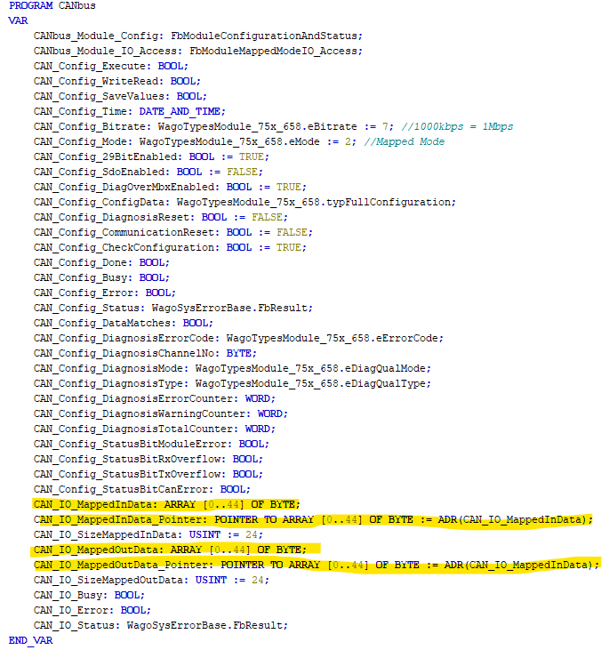
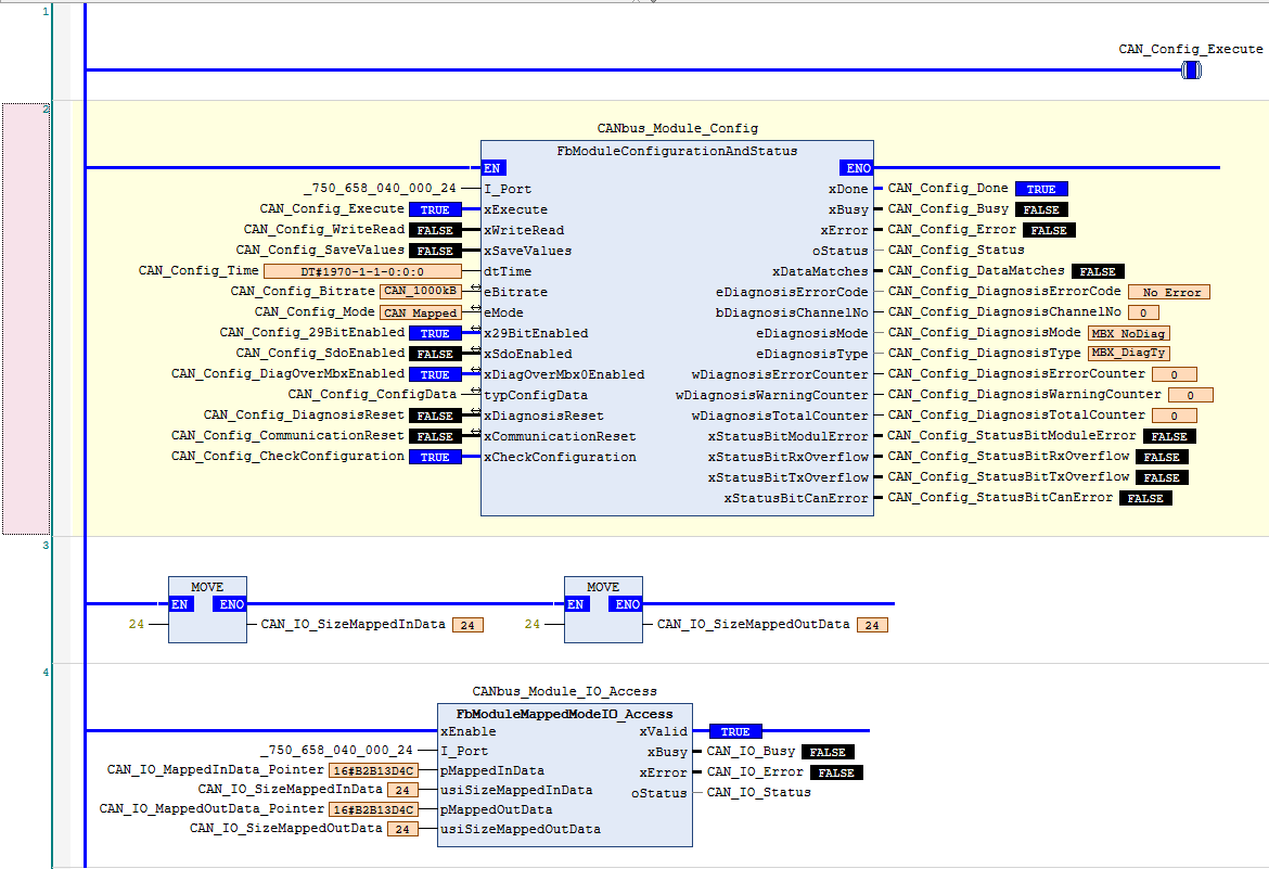
Its worth noting that even though I was able to map to the registers, the registers are not readily accessible to Codesys V3.5 like other IO cards. I hope Wago fixes this in later revisions. In order to be able to get the data into Codesys V3.5, I needed to use 2 function blocks that are included with the adapter library WagoSysModule_75x_658. FbModuleConfigurationAndStatus must be used no matter what, and if using Mapped mode, also FbModuleMappedModeIO_Access. One Gotcha is that the FbModuleMappedModeIO_Access uses pointers and the array of data needs to be created and addressed as a pointer before the pointer is used otherwise it send the processor into error.
If you dont end up mapping data - you will also need to use the WagoAppCanLayer2 library and use the functions in there to receive and send data (you will still need the FbModuleConfigurationAndStatus function block to activate and check the card each PLC scan).
See Codesys implementation Pictures below:
Hello, Thanks for the feedback, I would recommend you to send those feedback to your WAGO sales representative.